Boost and interleaved PFC inductors
Review energy storage, ripple, DC bias, switching frequency, core and copper loss across the operating range.
 Magnetic Component Engineering
PFC energy storage, differential-mode attenuation and common-mode noise suppression are different magnetic jobs. IKP reviews the waveform, current, impedance target, insulation, temperature and mechanical constraints before selecting a topology.
Product suitability, ratings, test conditions and compliance requirements are confirmed by IKP engineering before quotation.
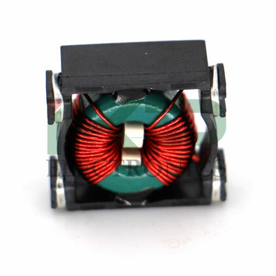
Use a standard family as the starting point, then confirm the project-specific electrical, insulation and thermal conditions.
Review energy storage, ripple, DC bias, switching frequency, core and copper loss across the operating range.
Define the differential noise band, target attenuation, current waveform, saturation margin and damping context.
Review common-mode impedance, leakage inductance, line current, insulation, creepage and temperature rise.
The same nominal inductance or impedance does not guarantee equivalent behavior under bias, frequency and temperature.
Provide input range, output voltage, switching strategy, ripple target and cooling conditions for the first calculation review.
Upload a PFC requirement →Share the line configuration, current, target noise band, insulation requirement and available filter envelope.
Browse choke structures →Start a custom feasibility review when the current, impedance, insulation, terminals or envelope cannot be met by a standard item.
Discuss custom magnetics →Separate PFC energy storage, differential-mode attenuation and common-mode suppression requirements.
Include input range, switching frequency, RMS/peak current, ambient, cooling and fault conditions.
Evaluate core, winding, impedance, leakage, creepage, clearance and the available mechanical envelope.
Confirm temperature, waveform and system-level EMI results against agreed project criteria.
A schematic excerpt, waveform or current part number can accelerate the first review.
IKP will identify the relevant topology, current product evidence and open validation items before a formal proposal.
Share the application, electrical requirements, mechanical limits, volume and timing. Please do not include personal information that is not needed for the project.